Guide
FPV Fiber Optic System Wiring and Setup Tutorial
by SkyVolt FPV Engineering Team · About the authors
In this guide
- Flight Controller Wiring
- Fiber Optic Connector Installation
- Ground Module Connection
- Video Output
- UART Port Configuration
This guide explains how to connect and configure an FPV fiber optic transmission system, including flight controller wiring, ground module installation, video output, and UART port settings.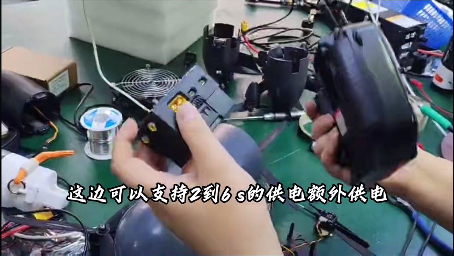
Flight Controller Wiring
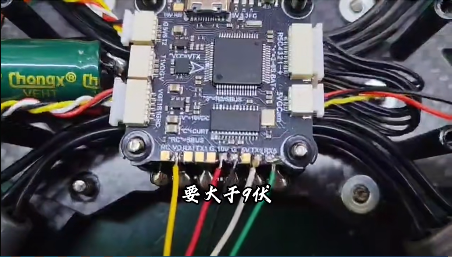
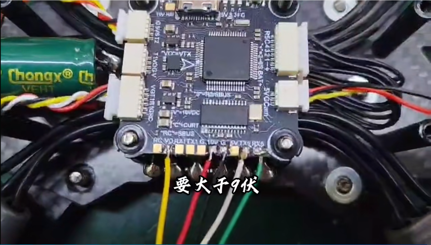
Connect the wires according to their colors:
- Yellow: Video signal (VIDEO)
- Red: Positive power (+), above 9V
- Black: Ground (GND)
- White: Flight controller TX
- Green: Flight controller RX
Make sure all connections are secure and correctly soldered.
Fiber Optic Connector Installation
- The connector has a specific orientation: flat side facing up and raised pin side facing down. Align it correctly and insert it into the socket.
Ground Module Connection
The ground module supports 2S–6S power input.
- Insert it into the radio transmitter's JR module bay, remove the fiber optic dust cap, connect the fiber cable, and tighten the locking nut.
Video Output
- Turn on the radio transmitter and check that the blue and red indicator lights are on. Connect an AV monitor using an RCA connector to display the video feed.
UART Port Configuration
Open Betaflight Configurator and enter the Ports tab.
Select the UART port corresponding to the physical wiring, save the settings, and restart the flight controller. Then open the Receiver tab to check whether the receiver works normally.
Important: The UART port configured in Betaflight must match the port used for physical wiring.
Conclusion
Follow these five steps to complete the FPV fiber optic system installation and configuration. Correct wiring and port settings are essential for reliable operation.